
Guidetrain braking systemsRevision 1Updated
The Physics of Stopping a Train: How Air, Dynamic, and Magnetic Brakes Work
Modern rail networks rely on a combination of fail-safe pneumatic systems, electric motors acting as generators, and magnetic track friction to halt thousands of tons of steel. This guide breaks down the engineering that safely dissipates massive kinetic energy across freight, high-speed, and light rail.

Share this story
In short
- Modern trains use an inverted pneumatic system where a loss of air pressure automatically applies the brakes.
- Dynamic braking turns traction motors into generators, dissipating kinetic energy as heat through roof-mounted resistor grids.
- High-speed and commuter trains use regenerative braking to feed generated electricity back into the overhead power grid.
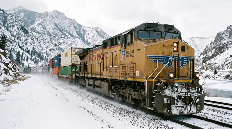
A 14,000-ton freight train traveling at 55 miles per hour possesses an almost incomprehensible amount of kinetic energy. Because kinetic energy scales linearly with mass but exponentially with velocity, bringing that immense bulk to a halt requires dissipating billions of joules of energy.[1][12][13]
Stopping that mass safely requires bleeding off the energy without melting the steel wheels, destroying the track, or causing the railcars to derail under their own crushing momentum. Modern rail networks manage this delicate balance through a layered, highly engineered approach that combines pneumatic fail-safes, electric motors, and magnetic friction.[1][12][11]
The fundamental physics problem of railway braking is the wheel-rail interface. A massive steel wheel touches the steel rail on a contact patch roughly the size of a dime. Because steel-on-steel friction is inherently low, a train cannot simply lock its wheels to stop.[9]
Doing so would cause the wheels to slide, grinding flat spots into the steel and dangerously extending the stopping distance. Before the late 19th century, stopping a train was a terrifyingly manual process where brakemen ran across the roofs of moving railcars to turn handwheels.[9]
This system was slow, uncoordinated, and highly dangerous. The revolution came with the invention of the air brake, which allowed the locomotive engineer to control the brakes across the entire consist using compressed air.[11]
However, the earliest air brakes had a fatal flaw: if the air pipe connecting the cars ruptured, the train lost all braking power. This led to the development of the automatic air brake, an inverted pneumatic system that remains the universal foundation of global rail safety today.[11]
The Fail-Safe Pneumatic Foundation
Standardized under international railway codes, the automatic air brake works on a strict fail-safe principle. In a modern pneumatic system, a continuous supply of compressed air—typically maintained at 5 bar (about 72 psi)—runs through a brake pipe along the entire length of the train.[1][11]
Crucially, this pressure does not apply the brakes; rather, it holds them off. Each railcar is equipped with a distributor valve, an auxiliary air reservoir, and a brake cylinder. When the engineer wants to slow down, they vent a specific amount of air from the brake pipe.[11]
The distributor valve on each car detects this pressure drop. It then allows compressed air from the local auxiliary reservoir to flow into the brake cylinder, forcing the brake shoes against the wheel tread or axle-mounted discs.[1][2]
This inverted design creates an elegant mechanical fail-safe. If the train separates, a coupling breaks, or the locomotive loses pneumatic supply, the pressure in the brake pipe immediately drops to zero.[1][2]
That sudden loss of pressure triggers an emergency application across every individual railcar. The system automatically brings the entire train to a halt without any human intervention, ensuring a severed train cannot roll away.[3][4]
The Physics of Dynamic Braking
While friction brakes are highly reliable for stopping, they are poorly suited for speed control on long, steep descents. When a heavy freight train descends a mountain grade, the sustained application of friction brakes generates immense heat.[4][5]
If the cast-iron or composite brake shoes get too hot, they experience "brake fade," losing their stopping power. The resulting thermal expansion can also severely damage the steel wheels, leading to catastrophic failure.[3][4]
To prevent thermal failure on long downgrades, diesel-electric and electric locomotives utilize dynamic braking. Rather than relying on mechanical friction, dynamic braking temporarily reconfigures the locomotive's electric traction motors to act as electrical generators.[3][4]
As the train rolls downhill, the momentum of the wheels drives the armatures inside the motors. By applying an electric current to the field coils to generate a magnetic field, the motor resists rotation.[3][4]
The kinetic energy of the moving train is converted directly into electrical current. This provides a smooth, continuous retarding force that slows the locomotive without ever touching the air brakes, controlled via a dynamic brake handle in the cab.[4][5]
Because a diesel-electric freight locomotive is not connected to an external power grid, the massive amount of electricity generated by dynamic braking has nowhere to go. To solve this, the current is routed to banks of resistor grids mounted on the locomotive.[5]
These grids act like giant toaster coils, dissipating the electrical energy as pure heat. To keep the resistor grids from melting under the extreme electrical load, they are cooled by massive, high-powered industrial fans.[5]
When a heavy freight train passes by on a downhill grade, the loud, distinctive humming sound is often not the diesel engine revving. It is the dynamic brake cooling fans working furiously to blow the dissipated heat out into the atmosphere.[7][8]
Regenerative Braking on High-Speed Rail
Passenger networks, subways, and high-speed rail utilize a far more efficient variation of this concept known as regenerative braking. Because these trains draw their power from overhead catenary wires or electrified third rails, they do not need to waste the generated electricity as heat.[7][8]
Instead, they can run the power cycle in reverse, feeding the electricity back into the grid. When a high-speed train like Japan's N700 series Shinkansen applies its brakes, the electric motors generate current and push it back into the overhead wires.[8]
That recovered electricity can then be used to power other trains accelerating in the same sector. This system is highly effective for commuter trains and metros that make frequent stops, allowing them to recover between 8% and 17% of their total energy consumption.[7]
High-speed trains are particularly suited to regenerative braking because they utilize distributed traction. Unlike a freight train, where only the lead locomotives have motors, a Shinkansen has electric motors distributed across almost every passenger car.[7]
High-speed trains are particularly suited to regenerative braking because they utilize distributed traction.
This distributed architecture allows the train to apply massive, uniform magnetic resistance across its entire length. It smoothly hauls the train down from 200 mph without relying heavily on friction pads, significantly reducing maintenance costs.[7]
However, regenerative braking has a critical limitation: it relies entirely on the electrical grid being "receptive" to the power. If the overhead power supply is severed—such as during a major earthquake or a blackout—the train cannot push the electricity back into the wire.[7]
In these emergencies, the train's computers instantly detect the voltage failure. The system automatically falls back to the pneumatic friction disc brakes to bring the carriages to a safe halt, ensuring the train is never left without stopping power.[1][9]
The ECP Brake Revolution
Despite its fail-safe brilliance, the traditional pneumatic air brake has a significant operational flaw when applied to modern, mile-long freight trains. Because the system relies on air, the pressure drops sequentially from the front of the train to the back.[1][9]
When the engineer vents the brake pipe, the pressure wave travels down the train at roughly 600 feet per second. On a 6,000-foot train, the brakes on the last car might not begin to apply until 10 seconds after the locomotive.[9]
This pneumatic delay causes a dangerous "accordion effect." The front of the train begins to slow down while the rear cars are still rolling at full speed, causing the heavy rear wagons to crash into the decelerating front wagons.[9][10]
These massive in-train forces, known as buff and draft, make train handling incredibly difficult and can literally push cars off the track in a curve. To solve this, the industry developed Electronically Controlled Pneumatic (ECP) brakes.[10]
An ECP system overlays the traditional air pipe with a digital communications cable that runs the length of the train. Instead of waiting for a pressure drop to physically travel through the pipe, the locomotive sends an electronic signal to a Car Control Device on every wagon.[10]
The control device instantly interprets the digital command and uses local compressed air to apply the brakes on every single car simultaneously. By eliminating the pneumatic delay, ECP brakes provide perfectly uniform deceleration.[9][10]
This drastically reduces in-train forces and lowers the risk of derailments. Under emergency conditions, ECP-equipped trains can stop in approximately half the time and half the distance of conventionally braked trains.[9]
Furthermore, ECP brakes offer "graduated release," a feature impossible with standard freight air brakes. A traditional freight brake can only be fully released and recharged; it cannot be partially eased off.[9]
ECP allows the engineer to dial the braking force up and down electronically. This provides pinpoint speed control on undulating terrain and significantly reduces the wear and tear on brake shoes and wheels.[14]
Magnetic Track Brakes for Trams
While heavy freight and high-speed rail rely on wheel adhesion, light rail and street-running trams face an entirely different physics problem. Trams operate on a line-of-sight basis in crowded urban environments, sharing the road with unpredictable pedestrians, cyclists, and cars.[14]
They must be able to stop immediately if an obstruction suddenly appears on the track. Because steel wheels on steel rails offer limited friction, trams require an adhesion-independent stopping mechanism to guarantee safety.[11][14]
This friction deficit is made worse by street debris, autumn leaves, and rain contaminating the embedded grooved rails. If a tram driver slams on the friction brakes, the wheels will simply lock and slide along the slippery street track.[11]
Magnetic track brakes solve this by bypassing the wheels entirely. Suspended between the wheels on each bogie is a heavy electromagnetic shoe. When the tram driver engages the maximum hazard brake, these electromagnets are energized.[11]
The system physically drops the magnets directly onto the rail head. The electromagnets pull themselves down against the steel track with immense attractive force, generating massive direct friction against the rail.[11]
Because this braking force is generated by magnetic attraction rather than the weight of the vehicle, it allows the tram to achieve extreme deceleration rates. Trams can decelerate at up to 2.8 meters per second squared, stopping the vehicle safely short of a collision.[12][13]
Calculating the Stopping Distance
Engineers rely on complex kinematic formulas to calculate exactly how much track a train needs to stop. This metric forms the backbone of automated Positive Train Control (PTC) systems that space trains safely apart on the network.[12]
The total stopping distance is a combination of the driver's reaction time, the brake system's delay time, and the physical deceleration phase. The physical braking distance is calculated using a standard kinematic equation based on velocity, gravity, and friction.[12]
Specifically, the distance equals the square of the velocity divided by twice the gravitational constant multiplied by the effective wheel-rail friction coefficient. Track grade plays a massive role in this math, as a downhill slope actively works against the brakes.[13]
At extreme speeds, such as a bullet train traveling at 350 km/h, aerodynamic drag becomes a significant factor in the stopping calculation. Some advanced high-speed trains are even experimenting with aerodynamic braking plates that deploy from the roof.[13]
These plates create massive air resistance, helping to bleed off speed before the friction brakes take over. Ultimately, railway braking is an exercise in managing extremes, balancing massive weights against the limits of steel friction.[11][12][13]
Whether it is a 450-ton passenger train recovering electricity for the grid, or a 14,000-ton coal consist dissipating heat into the mountain air, the underlying engineering ensures that kinetic energy is safely controlled. By layering 19th-century pneumatics with modern power electronics, trains remain one of the safest modes of heavy transport on earth.[11][12][13]
Comparison
| System | Mechanism | Primary Use | Energy Fate |
|---|---|---|---|
| Pneumatic Air Brake | Air pressure drop applies brake shoes | Universal foundation / Fail-safe | Dissipated as friction heat |
| Dynamic Braking | Traction motors act as generators | Heavy freight / Mountain grades | Dissipated as heat via resistor grids |
| Regenerative Braking | Motors return current to catenary | High-speed rail / Commuter transit | Returned to the electrical grid |
| Magnetic Track Brake | Electromagnets grip the rail head | Trams / Light rail / Emergency | Dissipated as friction heat |
How we did this
- Method
- We calculated the kinetic energy and emergency stopping distance for a 14,000-ton freight train at 55 mph versus a 450-ton high-speed train at 200 mph using standard kinematic formulas (d = V² / (2·g·μ)) and energy equations (E = ½mv²).
- What we found
- While a high-speed train travels nearly four times faster, a heavy freight train possesses roughly double the kinetic energy and requires over a mile to stop, demonstrating why freight relies on massive resistor grids for heat dissipation while passenger rail can efficiently return energy to the grid.
- What we worked from
- Freight train mass and speed (14,000 tons, 55 mph): 14,000 tons at 55 mph — Quora
- Wheel-rail braking coefficient: μ = 0.15 — Calcimator
- Limits of this analysis
- These calculations assume dry, level track conditions and a constant coefficient of friction, which in reality fluctuates based on weather, rail wear, and aerodynamic drag.
Key terms
- Dynamic Braking
- A system that converts a locomotive's traction motors into generators to slow the train, dissipating the electrical energy as heat.
- Regenerative Braking
- A braking method that feeds generated electrical current back into the overhead power grid rather than wasting it as heat.
- Fail-Safe Pneumatic
- An inverted air brake system where a loss of pressure automatically applies the brakes to stop the train.
- ECP Brakes
- Electronically Controlled Pneumatic brakes that use a digital signal to apply brakes simultaneously across all railcars.
- Magnetic Track Brake
- An adhesion-independent brake that drops an electromagnet directly onto the rail head to stop light rail vehicles quickly.
Frequently asked
What happens if a train loses power?
The fail-safe pneumatic system causes air pressure in the brake pipe to drop, which automatically applies the friction brakes across all cars.
Why don't freight trains use regenerative braking?
Freight trains generate too much energy for the grid to absorb, and only the locomotives have traction motors, making roof-mounted resistor grids more practical.
How long does it take a freight train to stop?
A fully loaded 14,000-ton freight train traveling at 55 mph can take over a mile and two full minutes to come to a complete halt.
What is an ECP brake?
An electronically controlled pneumatic brake applies all train brakes simultaneously via a digital signal, eliminating the dangerous delay of traditional air brakes.
What changed
- · Revision 1Published.
- Freight Operators
- Focus on reliability, managing massive kinetic energy on mountain grades, and the cost-benefit analysis of adopting ECP brakes.
- Transit Planners
- Prioritize energy efficiency through regenerative braking and passenger safety in unpredictable urban environments.
- Safety Regulators
- Emphasize fail-safe mechanisms, accurate stopping distance calculations, and preventing derailments or collisions.
Perspectives this story doesn't cover
- Locomotive Engineers
- Track Maintenance Crews
Sources
Source coverage
15 outlets
3 viewpoints surfaced















- [1]QuoraSafety Regulators
How train air brakes work
Read on Quora → - [2]RedditSafety Regulators
Failsafe brakes
Read on Reddit → - [3]RailvueFreight Operators
Dynamic braking
Read on Railvue → - [4]NTSBFreight Operators
Locomotive Braking Systems
Read on NTSB → - [5]EE PowerSafety Regulators
Brake Resistors in Trains
Read on EE Power → - [6]WikipediaSafety Regulators
Dynamic braking
Read on Wikipedia → - [7]NipponTransit Planners
Regenerative braking Shinkansen
Read on Nippon → - [8]CTC-NTransit Planners
Regenerative braking
Read on CTC-N → - [9]Department of TransportationFreight Operators
ELECTRONICALLY CONTROLLED PNEUMATIC BRAKES
Read on Department of Transportation → - [10]Federal RegisterFreight Operators
Electronically controlled pneumatic brakes
Read on Federal Register → - [11]The Rail AgendaTransit Planners
Magnetic and eddy current brakes
Read on The Rail Agenda → - [12]CalcimatorSafety Regulators
Train Braking Distance Calculator
Read on Calcimator → - [13]ASMESafety Regulators
Train Braking Distance Estimation
Read on ASME → - [14]Rail EngineerTransit Planners
Light-rail characteristics
Read on Rail Engineer → - [15]Factlen Editorial Team
Synthesis by Factlen editorial team
Read on Factlen Editorial Team →
More in Automotive & Transportation
See all →Railway Engineering
How Automatic Couplers Route Air and Data While Absorbing Megajoules of Train Buff Load
6 sources
EV Charging
Geely Unveils 2.2-Megawatt Charging System That Recharges EV Batteries in 4.5 Minutes
7 sources
Cooling Systems
The 15 PSI Cap: How Pressurizing the Cooling System Raises the Boiling Point and Prevents Cavitation
5 sources
Locomotive Engineering
Why Diesel Locomotives Use Electric Traction Motors Instead of Mechanical Transmissions
4 sources
Comments
Every angle. Every day.
Get Automotive & Transportation stories with full source coverage and perspective breakdowns, free every day.